| Index | wersja polska |
See the FX-700P system bus description.
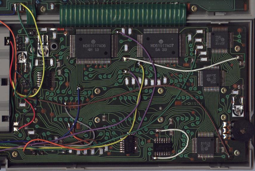
See the HD61914 chip description. The PB-700 uses 4 of them.
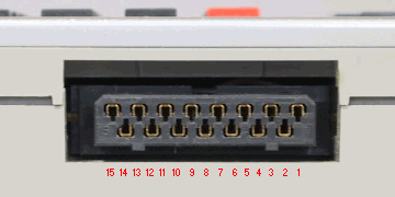
| Expansion Port Pin |
Symbol | Function |
|---|---|---|
| 1 | CE1 | chip enable of the printer interface, active low |
| 2 | GND | ground (positive supply voltage rail) |
| 3 | CE2 | chip enable of the cassette interface, active low |
| 4 | CK1 | bi-phase clock |
| 5 | INIT | output for the printer control signal INIT |
| 6 | CK2 | bi-phase clock |
| 7 | VDD3 | -5V when operational, 0V when stand-by |
| 8 | D1 | data 1 |
| 9 | BUSY | input for the printer status signal BUSY |
| 10 | D2 | data 2 |
| 11 | FAULT | input for the printer status signal FAULT |
| 12 | D3 | data 3 |
| 13 | OP | register select |
| 14 | D4 | data 4 |
| 15 | GND | ground (positive supply voltage rail) |
The cassette subsystem in the FA-4 interface is almost identical with the FA-3 one, so the tape interface protocol used by the FX-700P applies to the PB-700 as well.
However, there's an interesting quirk in the PB-700 protocol. The calculator writes to the tape more data than reads back. For example the last 3 bytes of the file header segment remain unread. To skip these data the calculator inserts a close/open sequence between the segments which causes loss of a few bytes read from the tape. This effectively places the tape head to the lead-in of the next file segment. Seems like a kludge to me...
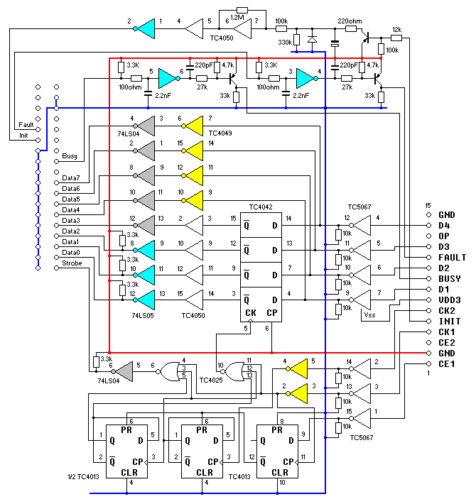
The printer communication protocol can be easily figured out from the circuit diagram of the FA-4 parallel port interface.